Inquire
squirrel cage induction motor circuit diagram
Induction motor - Wikipedia
Squirrel-cage induction motors are very widely used in both fixed-speed and variable-frequency drive applications.
Learn More
Squirrel-cage rotor - Wikipedia
Diagram of the squirrel-cage (showing only three laminations) The motor rotor shape is a cylinder mounted on a shaft. Internally it contains longitudinal conductive bars (usually made of aluminium or copper) set into grooves and connected at both ends by shorting rings forming a cage-like shape.
Learn More
5.6. Squirrel-cage Induction Motor
To be used for single drives only, circuit is not safe! Circuit diagrams for reversing contactor circuits (pulse and holding current locking). reversing
Learn More
Equivalent Circuit of a Double Cage Induction Motor
Equivalent Circuit of a Double Cage Induction Motor - For a double cage induction motor, the suffixes s and r are used to denote stator and
Learn More
PDF Control of MotorCharacteristics by Squirrel-Cage RotorDesignPDF
by Squirrel-Cage RotorDesign The reactance X2 in an induction motor equivalent circuit represents the referred form of the rotor's leakage reactance. Recall that leakage reactance is the reactance due to the rotor flux lines that do not also couple with the stator windings. In general, the far-394 CHAPTER 7INDUCTION MOTORS FIGURE 7-24
Learn More
What is a Squirrel Cage Induction Motor and Its Working
Squirrel induction motor working is based on the principle of electromagnetism. When the stator winding is supplied with a three-phase AC, it produces a
Learn More
When the equivalent circuit diagram of double squirrel-cage
When the equivalent circuit diagram of double squirrel-cage induction motor is constructed the two cages can be considered a) In series b) In parallel c) In
Learn More
1 UNIT III THREE PHASE INDUCTION MOTOR Constructional
cage, forming a closed electrical circuit. So the rotor is called squirrel cage rotor. • As the bars are permanently shorted to each other through end.
Learn More
Starting methods of 3 phase induction motor pdf
running trails las cruces; sims 3 newsea hair retextures; Newsletters; mexican art imports; striking testimonies; medicine ball tea chlorophyll; erythritol and liver disease
Learn More
Solved (a) Draw the equivalent circuit of the simplified
6 Marks) (b) Draw the power flow diagram of the squirrel cage induction motor [6 Marks] (c) What techniques are used to minimize induction motor core loses? [5 Marks] (d) A three-phase, 208V, four-pole and 60Hz squirrel cage induction motor is subjected to a no-load test at 60Hz, a locked rotor test at 15Hz, and a DC test.
Learn More
Torque-Speed Characteristics of Three Phase Squirrel Cage
Figure 5: Circuit diagram for V/f control The cut section of a squirrel cage induction motor is shown in Fig.6. Separate view of the stator and rotor of an induction motor is shown in Fig.7. 4. Figure 6: Cut section of an Induction motor (a) (b) Figure 7: a) Stator b) Rotor References
Learn More
Wound Rotor Induction Motor: What is it? (Diagram & Speed Control
In squirrel cage induction motors, the rotor bars are permanently short-circuited at the end rings hence external resistance cannot be connected whereas, in slip ring induction motor external star connected resistance is connected in the rotor circuit. Other differences between the two motors are discussed in the table below.
Learn More
Single Phase Induction Motor - Construction, Diagram, Working Principle
A single-phase induction motor with a distributed stator winding and a squirrel-cage rotor is shown in Figure 4. When the stator winding of a single phase induction motor is connected to single phase ac supply, a magnetic field is developed, the axis of this magnetic field is stationary in the horizontal direction as shown in the Figure 4.
Learn More
Direct Starting Of Squirrel-Cage Induction Motors
Direct Starting Of Squirrel-Cage Induction Motors. With direct starting, the poles of contactor and motor protective device are connected to the pole conductors (Figure 1) and the operating current of the motor flows through them. Figure 1 – Example of a two-component starter for direct starting consisting of a motor protection circuit
Learn More
Modelling and Analysis of Squirrel Cage Induction Motor with
The electrical system of this machine as described by Equations (80)&(84)-(87) can be represented with an equivalent circuit. The zero sequence circuit diagram
Learn More
Starting Three-Phase, Squirrel-Cage Induction Motors
The wiring diagram for a typical across-the-line magnetic starter is illustrated in 1 A. The three heavy contacts are in the three line leads feeding the motor.
Learn More
Lab-3: Squirrel-Cage Induction Motor - Department of
motor per-phase equivalent circuit Fig. 1: Induction motor per-phase equivalent circuit. This equivalent circuit and the equations discussed in class assume a symmetric Y-connected winding. Based on the determined parameters, the students will develop a steady-state model (equivalent circuit) of the given motor, and then use the model to
Learn More
3 phase induction motor block diagram
Basic block diagram of optical fiber communication system consists of following important blocks . 1. Transmitter. 2. Information channel. 3 . Receiver. Fig. 1 shows block diagram of OFC system.
Learn More
ELECTRICAL MACHINE-II - VSSUT
phasor diagram, equivalent circuit, power and torque The rotor of the squirrel cage motor shown in Fig: 3.1(b) contains no windings. Instead it is a.
Learn More
Direct Online Starter (DOL Motor Starter) : Circuit
The DOL starter is suitable for small rating three phase squirrel cage induction motor. Direct Online Starter Circuit Diagram. The Direct online starter circuit diagram can be divided into
Learn More
Squirrel cage blower - drweor.luckytee.shop
metformin and saxenda together for weight loss jimin bts wattpad
Learn More
Starting methods of three phase induction motors
Starting in-rush current in squirrel cage motors is controlled by applying reduced voltage to the stator. These methods are sometimes called as reduced voltage
Learn More
Adadelta-Based BPANN Controller for Online Equivalent
A squirrel cage induction motor includes: a stator core (11); a plurality of stator slots (12) radially disposed in a circumferential direction of the stator core (11) with predetermined intervals
Learn More
Induction Motor MCQs Part 6
7 A pump induction motor is switched on to a supply 30% lower than its rated voltage and the pump runs. What will ultimately happen; 8 Cogging in an induction motor can be avoided using; 9 In equivalent circuit diagram of double squirrel-cage induction motor is constructed the two cages can be considered
Learn More
Wiring Diagram For Squirrel Cage Motor - Diysise - Blogger
Squirrel cage capacitor wiring diagram. The fan motor will have one or two wires, usually brown, that lead to a capacitor. A short summary of this paper. These diagrams are
Learn MoreDifference Between Slip Ring & Squirrel Cage Induction Motor
The motor whose rotor is wound type such type of motor is called slip ring induction motor, whereas the squirrel cage motor, has a squirrel cage type rotor. The rotor of the slip ring motor has a cylindrical core with parallel slots, and each slot consists each bar. The slot of the squirrel cage motor is not parallel to each other.
Learn More
Squirrel cage rotor circuit | Download Scientific Diagram
Download scientific diagram | Squirrel cage rotor circuit from publication: Instantaneous Phase Variation (IPV) for rotor bar fault detection and diagnosis | This paper presents a simulation
Learn More
What is Squirrel Cage Induction Motor? Working
Fig. 4. Schematic representation of a 3-phase squirrel cage induction motor. Characteristics of Squirrel Cage Induction Motor. Starting current: The starting current is about 5 to 6 times the
Learn More
Lecture 6 || Working of Squirrel cage Induction Motor
AC Machines: Working of Squirrel cage Induction Motor Topics discussed:1. Construction of a Squirrel cage induction motor2. Working of a Squirrel cage induc
Learn More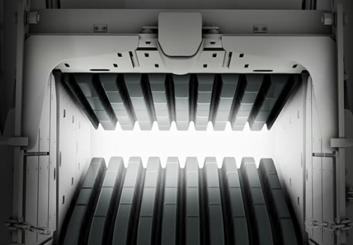
Recommendation Diagram Of Squirrel Cage Induction Motor 3 Way Rotary
As shown in the diagram above the parts 1 2 and 8 makes up the stator of the three phase induction motor. The short circuit current and the angle obtained from block rotor test is. A 3 phase squirrel cage induction motor is a type of three phase induction motor which functions based on the principle of electromagnetism it is called a squirrel
Learn More
Single Phase Induction Motor – Construction, Diagram, Working
A single-phase induction motor with a distributed stator winding and a squirrel-cage rotor is shown in Figure 4. When the stator winding of a single phase induction motor is connected to single phase ac supply, a magnetic field is developed, the axis of this magnetic field is stationary in the horizontal direction as shown in the Figure 4.
Learn More